

Understanding the role of a continuity tester in electrical diagnostics is crucial for professionals and enthusiasts alike. This guide offers a step-by-step approach to using a digital multimeter as a continuity tester, ensuring precise and safe measurements.
Whether testing switches and fuses or making general electrical connections, mastering a continuity tester is critical to effective electrical troubleshooting.
Setting Up Your Digital Multimeter for Testing
First, properly setting up your digital multimeter for the test is essential. This involves:
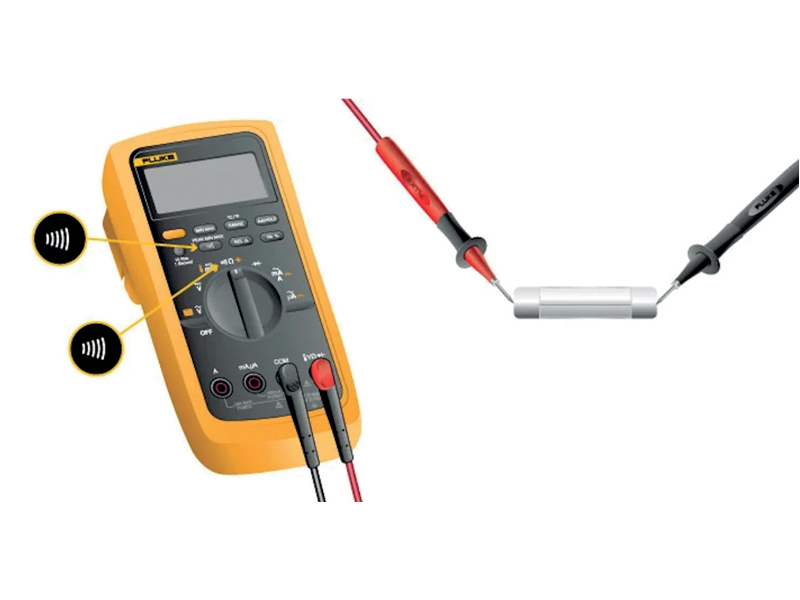
- Selecting the Correct Mode: Turn the dial to Continuity Test mode. This mode is often combined with other functions, typically resistance (Ω). The multimeter’s display may show OL and Ω with the test probes separated.
- Activating Continuity Mode: Some models require pressing a continuity button to activate this specific testing mode. If your multimeter has this feature, ensure this step is followed.
Executing the Continuity Test: Step-by-Step Instructions
Once your digital multimeter is set up, follow these steps to conduct the test:
- Connecting Test Leads: Insert the black test lead into the COM jack. Then, insert the red lead into the VΩ jack. Always remove the leads in reverse order after testing: red first, then black.
- Testing the Circuit: Connect the test leads across the tested component with the circuit de-energised. The position of the test leads is arbitrary, but ensure the component is isolated from other components in the circuit.
- Interpreting Results: The digital multimeter (DMM) emits a beep if a complete path (continuity) is detected. If the circuit is open (the switch is in the OFF position), the DMM will not beep.
- Concluding the Test: When finished, always turn the multimeter OFF to conserve battery life.
Understanding Continuity Testing: Principles and Practices
Continuity is the presence of a complete path for the current flow. A circuit is considered complete when its switch is closed. Here are some key points to remember:
- Applications of Continuity Testing: A digital multimeter’s Continuity Test mode is versatile and suitable for testing switches, fuses, electrical connections, conductors, and other components. For example, a good fuse should show continuity.
- Audible Indicator: The beep is an audible response from the DMM when it detects a complete path, allowing technicians to focus on the test without constantly monitoring the display.
- Understanding Resistance and Beeps: The beep is triggered based on the resistance of the tested component, influenced by the multimeter’s range setting. For instance, at a 400.0 Ω range setting, a multimeter typically beeps if the component has 40 Ω or less resistance.
- Optimal Range Setting: Use the lowest range setting to test components with low-resistance values, such as electrical connections or switch contacts.
Comtest
Tel. +27 10 595 1821
sales@comtest.co.za
www.comtest.co.za
Facebook: bit.ly/3iuk4cg
YouTube: bit.ly/2V4nc6j
LinkedIn: bit.ly/3rpTu86
Product: https://tinyurl.com/vxs94z32